6 Lead 480V Motor Wiring : Diagram Distribution Transformer Bank Wiring Diagram Full Version Hd Quality Wiring Diagram Zodiagramm Mbreporter It. On the motor there is a low voltage wiring and a high voltage wiring. Some work, some do nothing, some destroy it. Always use wiring diagram supplied on motor nameplate. On the motor wiring diagram, one of the lines feeds p1 always, no switching) thanks in advance for any thoughts you may have on this. The six leads are numbered 1,2,3,6,7,8 or it's 1,2,3,7,8,9.
Those nine leads provide an option for supplying power from either high or low voltage sources. 480 volt motor wiring diagram. On six lead single voltage motors watch out and check the manufacturer diagrams. On the motor there is a low voltage wiring and a high voltage wiring. W2 cj2 ui vi wi w2 cj2 ui vi wi a cow voltage y high voltage z t4 til t12 10 til t4 t5
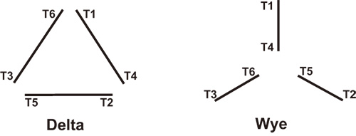
Practical Machinist Largest Manufacturing Technology Forum On The Web from www.practicalmachinist.com This will give you the relationship between the b and c wires. Delta is the diagram where l1 goes to both u1 and w2. A three phase motor is more efficient than a single phase motor because of the peculiarities of alternating current ac. Connections to 460 volts will be 1+6 to l1, 2+4 to l2, 3+5 to l3. Click on the image to enlarge, and then save it to your computer by right clicking on the image. 3 phase motor wiring diagram 12 leads. Each kit makes three splices. Coils ii, iii, and iv are permanently connected and cannot be separated.
In either case, you first have to figure out which leads are pairs as charles described.
On six lead single voltage motors watch out and check the manufacturer diagrams. 480 volt motor wiring diagram. On the motor wiring diagram, one of the lines feeds p1 always, no switching) thanks in advance for any thoughts you may have on this. The six leads are numbered 1,2,3,6,7,8 or it's 1,2,3,7,8,9. In either case, you first have to figure out which leads are pairs as charles described. This reduces the wire cost and often simplifies manufacturing. Y is the diagram on page 22 where u2,v2,w2 are joined together. Furthermore, wiring diagram gives you the time frame by which the projects are to be completed. Connections to 460 volts will be 1+6 to l1, 2+4 to l2, 3+5 to l3. Each kit makes three splices. I have a 277480 volt panel. Typical wiring diagrams always use wiring diagram supplied on motor nameplate connection diagrams (#co leads part winding) weg three phase motors volts / 12 lead / part winding 12 10 11 12 3 l1 l2 12 10 11 64 5 78 9. This will give you the relationship between the b and c wires.
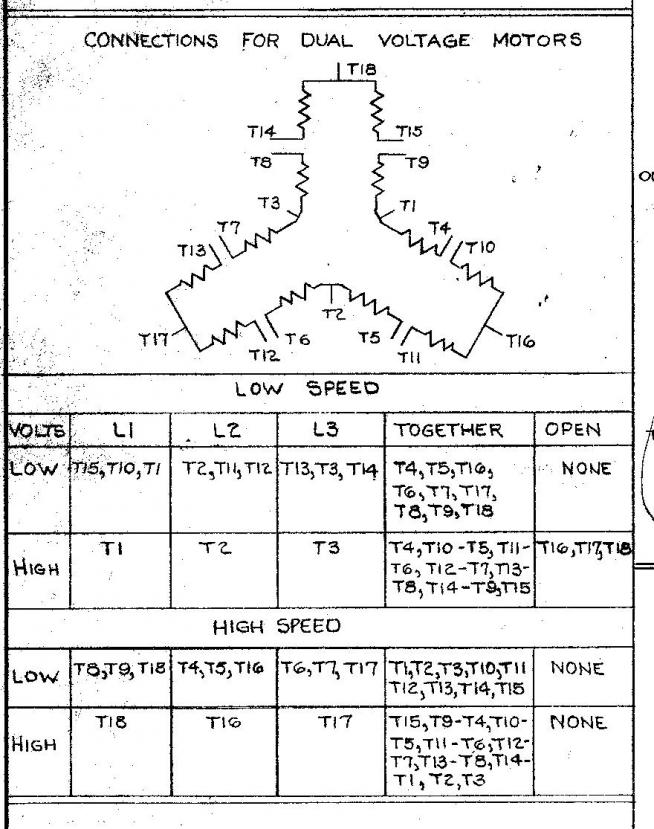
The above name plate belongs to one single winding/two speed motor. This will give you the relationship between the b and c wires. 480 volt motor wiring diagram. 12 leads terminal wiring guide for dual voltage delta connected ac induction motor. Follow the book every time.
Difference Between 4 Wire 6 Wire And 8 Wire Stepper Motors National Instruments from knowledge.ni.com There are about two dozen ways to wire it up total. Sound like a smart a$$, but this is important} if you get to the stage whereby a voltage is produced, then mark the b wire at the junction with c as b1. Here is a sample wiring diagram: Click on the image to enlarge, and then save it to your computer by right clicking on the image. L1 to t1, l2 to t2, l3 to t3, t4 to t7, t5 to t8 and t6. Typical wiring diagrams always use wiring diagram supplied on motor nameplate connection diagrams (#co leads part winding) weg three phase motors volts / 12 lead / part winding 12 10 11 12 3 l1 l2 12 10 11 64 5 78 9. This video is brought to you by: I had all the wire numbers fall off with the exception of #2.
I have a 277480 volt panel.
Typical wiring diagrams always use wiring diagram supplied on motor nameplate connection diagrams (#co leads part winding) weg three phase motors volts / 12 lead / part winding 12 10 11 12 3 l1 l2 12 10 11 64 5 78 9. Phase heater wiring diagram on 480v 3 phase heater wiring diagram. And the main voltage is 480 v. I have to hook up a 50hp 480v motor, the schematic is gone. On the motor wiring diagram, one of the lines feeds p1 always, no switching) thanks in advance for any thoughts you may have on this. Mark the c wire at the multimeter as c1. 480 volt motor wiring diagram. Collection of 6 lead motor wiring diagram. This reduces the wire cost and often simplifies manufacturing. The delta connection is for the low voltage. Here is a sample wiring diagram: Electrical motors 12 lead, dual voltage, wye start/delta run, both voltages or 6 lead, single voltage, wye start/delta run motors designed by us motors for wye start, delta run may also be used for across the line starting using only the delta connection. Connections to 460 volts will be 1+6 to l1, 2+4 to l2, 3+5 to l3.
Wiring diagram 2 speed motor 3 phase new two speed motor wiring. Phase heater wiring diagram on 480v 3 phase heater wiring diagram. In either case, you first have to figure out which leads are pairs as charles described. Each kit makes three splices. 3 phase motor wiring diagram 12 leads.
Why Wye Why Delta Pumps Systems from www.pumpsandsystems.com The delta connection is for the low voltage. Most use the high voltage wiring diagram only. There are 2 standard ways to correctly wire a 6 lead motor. W2 cj2 ui vi wi w2 cj2 ui vi wi a cow voltage y high voltage z t4 til t12 10 til t4 t5 Follow the book every time. Always use wiring diagram supplied on motor nameplate. Collection of 3 phase 6 lead motor wiring diagram. On the motor there is a low voltage wiring and a high voltage wiring.
Coils ii, iii, and iv are permanently connected and cannot be separated.
Always use wiring diagram supplied on motor nameplate. Follow the book every time. This video is brought to you by: For specific leeson motor connections go to their website and input the leeson catalog # in the review box, you will find connection data, dimensions, name plate data, etc. You may be able to understand precisely if the projects should be completed, that makes it much easier to suit your needs to correctly control your. Phase heater wiring diagram on 480v 3 phase heater wiring diagram. Mark the c wire at the multimeter as c1. Y is the diagram on page 22 where u2,v2,w2 are joined together. Each kit makes three splices. Each part ought to be placed and connected with other parts in particular way. Click on the image to enlarge, and then save it to your computer by right clicking on the image. The 6 leads are what's throwing me. Otherwise, the arrangement will not work as it ought to be.